
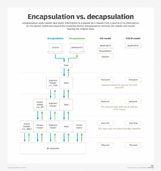
Encapsulation is the process where data is wrapped layer by layer with headers (and sometimes trailers) so it can be transmitted across the network; decapsulation is the reverse process on receipt.
Facts / key topics
- OSI layers: L7 → L1 (encapsulation), L1 → L7 (decapsulation)
- Data units: L7–L5: Data · L4: Segment (TCP) / Datagram (UDP) · L3: Packet · L2: Frame · L1: Bits
- Headers/trailers: L4: TCP/UDP header · L3: IP header · L2: Ethernet header + FCS trailer
- CCNA vs CCNP: CCNA – understand the process and the layers; CCNP – consequences for forwarding, MTU, QoS, tunnels, troubleshooting
Why does it exist? (problem definition)
- Networks must transport application data independently of media and protocol.
- Without encapsulation: no addressing, no port numbers, no reliability, no delivery.
- Typical scenarios: client → server communication, routing between networks, VPN / tunnels (extra encapsulation).
How does it solve the problem?
- Each OSI layer adds its own information (metadata) to the payload: L4 session control (ports, reliability) · L3 logical addressing and routing · L2 local delivery on the link.
- The receiver removes the layers one by one and delivers the data to the correct application.
How it works (step by step)
Step 1 – Initiation (sender): the application generates data (e.g. an HTTP request).
Step 2 – Encapsulation:
- L4: TCP/UDP header (src/dst port, seq/ack if TCP)
- L3: IP header (src/dst IP, TTL, protocol)
- L2: Ethernet header (src/dst MAC) + FCS
- L1: converted to bits on the media
Step 3 – Normal transit: a switch only looks at the L2 header; a router removes L2, reads L3 and builds a new L2 header (re-encapsulation).
Step 4 – Decapsulation (receiver): L2 → L3 → L4 → L7; data is delivered to the correct application via the port number.
Key concepts & terminology
| Concept | Explanation |
|---|---|
| Payload | Data from higher layers |
| Header | Control information added by a layer |
| Trailer | e.g. FCS for error detection |
| Re-encapsulation | New L2 header at every hop |
| MTU | Maximum frame size including headers |
Main elements (facts table)
| Element | Description | CCNA | CCNP |
|---|---|---|---|
| OSI layers | Layering of functions | ✔ | ✔ |
| Headers | Metadata per layer | ✔ | ✔ |
| Re-encapsulation | New L2 per hop | ✔ | ✔ |
| MTU / overhead | Fragmentation / tuning | ✖ | ✔ |
Dependencies & special considerations
- MTU: extra headers (VPN, GRE, IPsec) can cause fragmentation
- IPv4 vs IPv6: header differences (e.g. no checksum in IPv6)
- Security: IPsec encapsulates after L3
- Performance: more headers = more overhead
Advanced features (CCNP)
- Tunneling (GRE, VXLAN, IPsec) → nested encapsulation
- QoS markings (DSCP) are read in the L3 header
- Fragmentation vs PMTUD as a design choice
Configuration (Cisco IOS / IOS-XE)
No direct “encapsulation command” – the process is implicit. Related verification:
show interfaces
show ip route
show ip cef
ping / traceroute
Troubleshooting
Typical faults: ❌ wrong MTU → packet drops · ❌ ACL blocks based on L4/L3 headers · ❌ missing route → L3 packet dropped.
show interfaces
show ip route
show ip cef
debug ip packet
Design & best practices
- Know where encapsulation changes (router hops, tunnel entry/exit)
- Avoid unnecessary encapsulation in performance-critical paths
- Adjust MTU/MSS when using tunnels
Exam tips ⚠️
- “Router hop” → think re-encapsulation
- “MTU” mentioned → think headers + overhead
- CCNA asks what, CCNP asks what happens if…
Quick summary
- Encapsulation = wrap data layer by layer; decapsulation = unwrap it
- L2 changes at every hop; L3/L4 handle delivery and sessions
- MTU and overhead are classic traps
| Level | Expectation |
|---|---|
| CCNA | Understand process and layers |
| CCNP | Troubleshooting, design, edge cases |